APPLICATION NOTE
Characterisation of FNET Airplane Test Fixtures and Multiport Port De-embedding Matrices
Download PDF
On This Page
Objective
The objective of this procedure is to characterise the S matrix of a test fixture in order to use this matrix to remove the effect of the test fixture from a set of results calibrated and the end of the test cables.
This method means that a calibration can be simply performed at the ends of the test leads, for example with an Ecal unit (or SMA calibration standards), and a previously calculated and stored S-matrix can then be recalled to effectively calibrate out the test fixtures. In doing so the calibration process is greatly simplified and significantly reduces the time taken to calibrate the setup.
This procedure focuses on the example of FNET Airplane fixtures, however the techniques can be applied to any set of mixed mode test fixtures.
This procedure describes characterisation of a single unbalanced 4 port S-Matrix which describes a single balanced port of the Test Fixture. The procedure can be used to calculate all 8 or 16 ports of the test setup, or the resulting characterisation of the fixture can then be used to directly measure the S-Matrices of the other ports.
This procedure also provides instructions regard how to characterise the fixture as an 8 or 16 port device.
Method
General Considerations
The accuracy of this procedure is greatly dependent on consistency of measurements, and extreme care should be taken to avoid any movement of test fixtures, probes or cables during each of the measurements.
It is recommended to repeat this process several times in order to confirm the results of the characterisation.
It is recommended that averaging of 3 sweeps (minimum) is used for every measurement.
All results are to be taken in complex format (Re/Im).
Calibration
Before beginning this process, the NA must be calibrated for a full 4 port calibration including isolation at the ends of test cables using an Ecal module or SMA artefacts.
The Ecal is recommended.
Label Fixtures
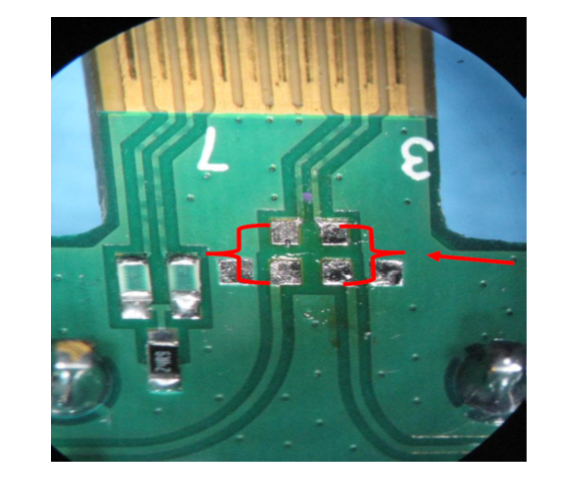
Carefully label all ports of the both Near and Far end Test Fixtures.
The labelling shall include both the balanced measurement port, and consistent numbering for the connections to the network analyser.
In the case that a multiport switch is used, it may also be helpful to add the switch connection port to the labelling for network analyser port to aid easy connection to the switch and ensure a constant path through the switch to the designated network analyser ports.
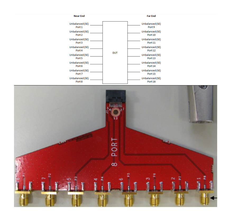
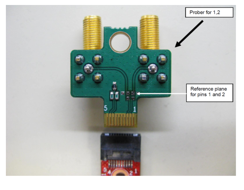
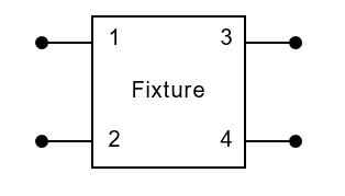
Explanation of port labeling
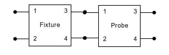
Characterise Probe for 2 Port De-embedding
In order to characterise the IL and FEXT transmission S-Parameters of the test fixture, this method utilises a “probe” fixture to interface to the Port 3 and Port 4 of the test fixture.
In the example of the FNET Airplane fixtures, it is possible to use a series of probe fixtures as such a probes.
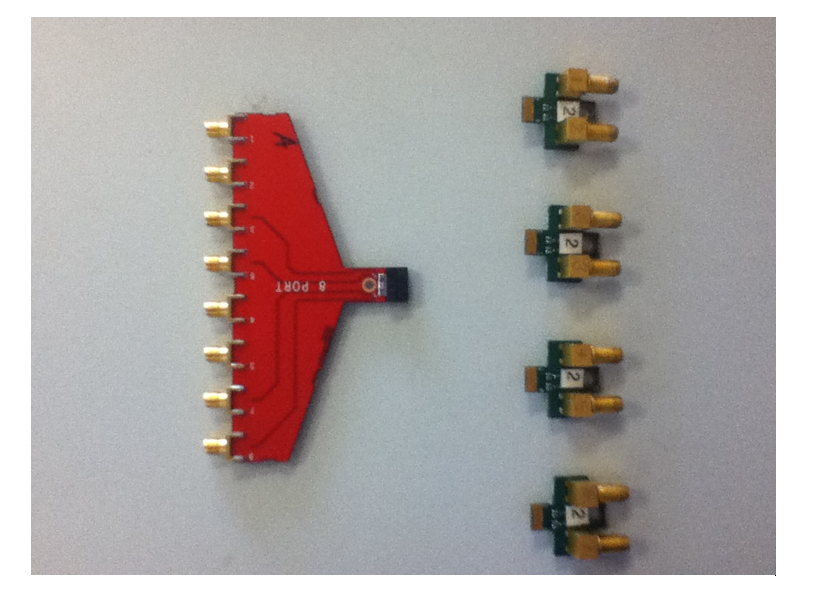
In the following example, the Port 9 and 10 are used as a probes, however this is arbitrary as all ports will be used for characterisation of the complete fixture.
Single Ended Measurements
- Connect Port 3 of the NA to Port 3 of Probe 3.
- Connect Port 4 of the NA to Port 4 of Probe 4.
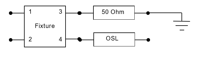
- Term Probe with load Resistor (terminating S33 & S44 with 50 Ohm).
- Measure S33Load and S44Load.
- Measure S34Load and S43Load.
- Term Probe with Open cal (terminating S33 & S44 with open.
- Measure S33Open and S44Open.
- Term Probe with Short cal (terminating S33 & S44 with short).
- Measure S33Short and S44Short.
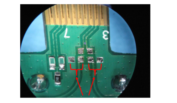
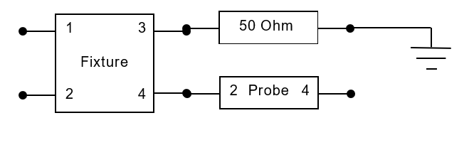
After these measurements have been taken the probe should be prepared for though measurement. By soldering 0 Ohm or 50 Ohm to ground resistors in the positions shown.
This 4 port procedure uses a total of 12 probes, 4 of these connect as 4 port probes to the pairs the ports 9-10, 11-12, 13-14 and 15, 16. The following 8 probes connect to the a single port in each pair, with the other pair being terminated directly with 50 Ohm to ground..
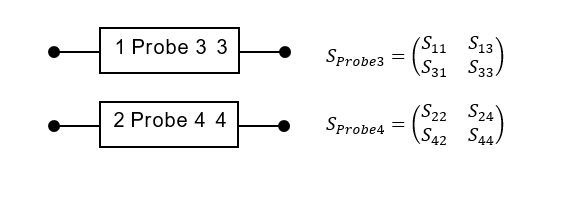
Calculate 2 Port S-Matrices of Probe
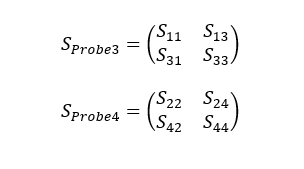
The measurements taken in the previous section can be used to calculate the 2 Port S-matrices of each of the unbalance port in the balance port of Probe
Each of these should be calculated to give:
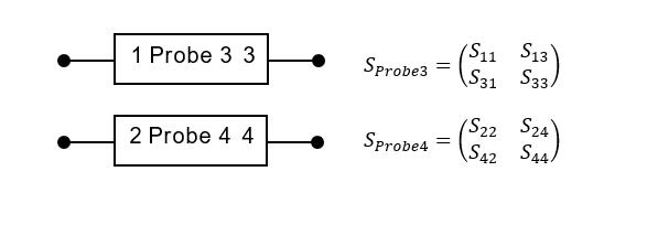
The mathematics to calculate these 2 port matrices is described in Annex A.
These probe matrices can then be used to de-embed from the results achieved as required when using the probe to measure transmission parameters of the fixture.
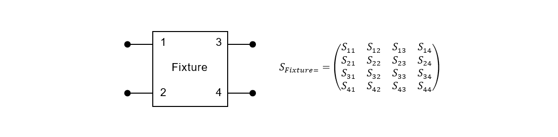
Characterisation of 4 port Test Fixture S Matrix terms
The following procedure can be used to characterise the S-Matrix terms for any 4 port device.
The example used in the rest of this clauses is that of balanced Port 1N (SE Ports 1 and 2) of an airplane fixture. The process must be repeated for all 8 balanced ports of a pair of fixtures.
Although it is possible to shortcut this process by using the 4 Port matrix calculated for a given port to directly measure the 4 Port matrices for all other balanced ports, it is recommended that each balanced port (and SE Port) is characterised by direct measurements where possible.
It can be helpful in understanding the SE port notation in the following sections as representing a direct connection of SE ports 1 and 2 of the near end fixture to the VNA ports required to measure IL, i.e. VNA port 1 has a through connection to VNA port 3, and VNA port 2 a through connection to VNA port 4.
This 4 port process should be considered the minimum required to perform successful de-embedding, but can be improved by moving to an 8 port or 16 port process, see Sections 5 and 6.
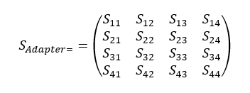
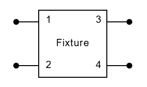
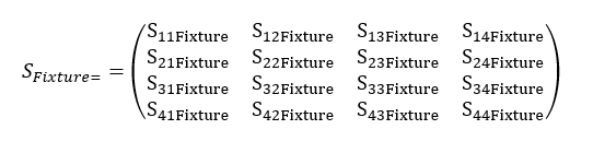
The object of characterising the 4 port Fixture is to populate every element of the following matrix.
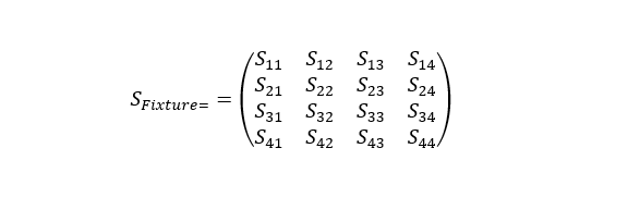
This can be achieved by the instructions provided in Section 4.
RL S-Parameters
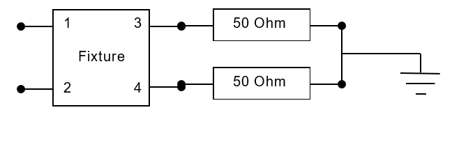
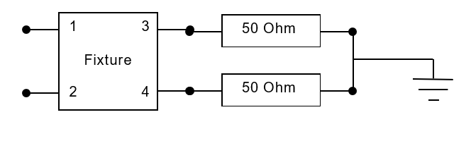
S11
- Connect Port 1 of the NA to Port 1 of the Fixture.
- Connect Port 2 of the NA to Port 2 of the Fixture.
- Terminate Port 3 of the Fixture with 50 Ohms to ground at the calibration plane.
- Terminate Port 4 of the Fixture with 50 Ohms to ground at the calibration plane.
- Measure S11 of the Fixture.
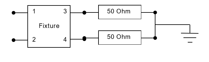
- Provide the result S11Fixture.
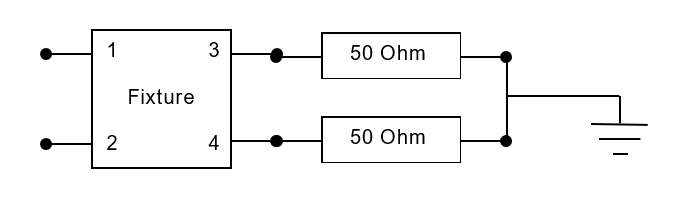
S22
- Connect Port 1 of the NA to Port 1 of the Fixture.
- Connect Port 2 of the NA to Port 2 of the Fixture.
- Terminate Port 3 of the Fixture with 50 Ohms to ground at the calibration plane.
- Terminate Port 4 of the Fixture with 50 Ohms to ground at the calibration plane.
- Measure S22 of the Fixture.
- Provide the result S22Fixture.
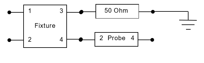
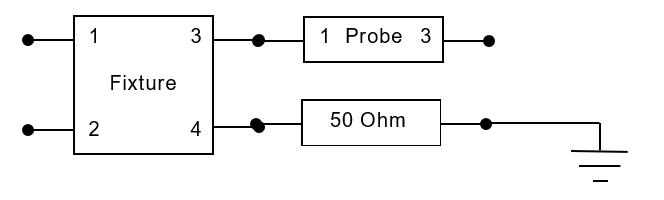
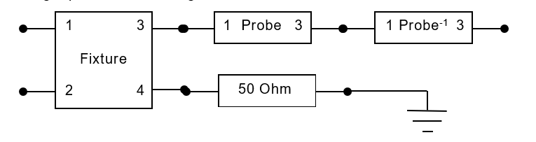
S33
- Connect Port 1 of the NA to Port 1 of the Fixture
- Connect Port 2 of the NA to Port 2 of the Fixture
- Connect Port 3 of the NA to Port 3 of the Probe
- Terminate Port 4 of the Fixture with 50 Ohms to ground at the calibration plane.
- Measure S33 of the Fixture and Probe.
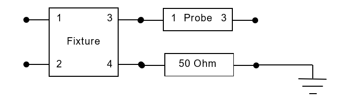
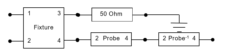
- De-embed 2 port S-matrix of the probe, SProbe3, from the measurement using the cascading 2 port de-embedding method shown in Annex B.
- T33Fixture= T33Probe-1T33Fixture+Probe
- Implies the result S33Fixture.
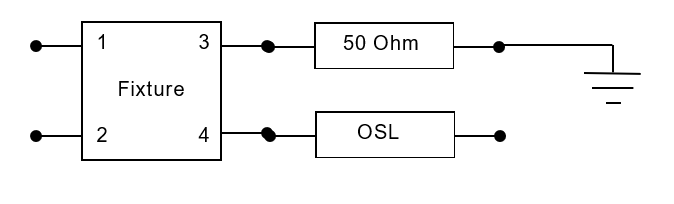
S33 Alternative
- Connect Port 1 of the NA to Port 3 of the Fixture.
- Connect Port 2 of the NA to Port 3 of the Fixture.
- Terminate Port 4 of the Fixture with 50 Ohms to ground at the calibration plane.
- Terminate Port 3 of the Fixture with 50 Ohms to ground at the calibration plane.
- Measure S11Load.
- Terminate Port 3 of the Fixture with Open cal at the calibration plane.
- Measure S11Open.
- Terminate Port 3 of the Fixture with Short cal at the calibration plane.
- Measure S11Short
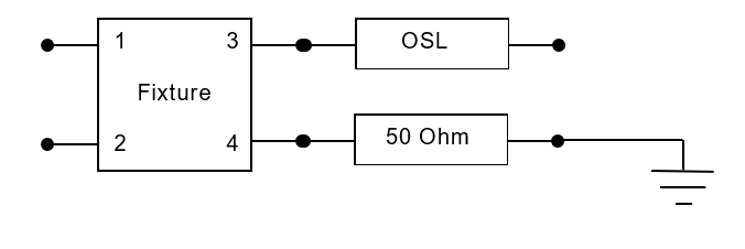
- Use the results S11Load, S11Open, and S11Short with the equations in Annex A.
- Implies the result S33Fixture.
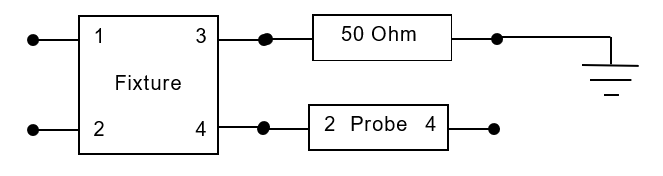
S44
- Connect Port 1 of the NA to Port 1 of the Fixture
- Connect Port 2 of the NA to Port 2 of the Fixture
- Terminate Port 3 of the Fixture with 50 Ohms to ground at the calibration plane.
- Connect Port 4 of the NA to Port 4 of the Probe
- Measure S44 of the Fixture and Probe.
- De-embed 2 port S-matrix of the probe, SProbe4, from the measurement using the cascading 2 port de-embedding method shown in Annex B

- T44Fixture= T44Probe-1T44Fixture+Probe
- Implies the result S44Fixture.
S44 Alternative Procedure
- Connect Port 1 of the NA to Port 1 of the Fixture.
- Connect Port 2 of the NA to Port 2 of the Fixture.
- Terminate Port 3 of the Fixture with 50 Ohms to ground at the calibration plane.
- Terminate Port 4 of the Fixture with 50 Ohms to ground at the calibration plane.
- Measure S22Load.
- Terminate Port 4 of the Fixture with Open cal at the calibration plane.
- Measure S22Open.
- Terminate Port 4 of the Fixture with Short cal at the calibration plane.
- Measure S22Short
- Use the results S22Load, S22Open, and S22Short with the equations in Annex A.
- Implies the result S44Fixture.
IL S-Parameters
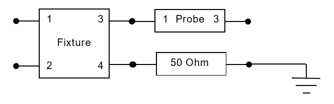
S13
- Connect Port 1 of the NA to Port 1 of the Fixture.
- Connect Port 2 of the NA to Port 2 of the Fixture.
- Terminate Port 4 of the Fixture with 50 Ohms to ground at the calibration plane.
- Terminate Port 3 of the Fixture with 50 Ohms to ground at the calibration plane.
- Measure S11Load.
- Terminate Port 3 of the Fixture with Open cal at the calibration plane.
- Measure S11Open.
- Terminate Port 3 of the Fixture with Short cal at the calibration plane.
- Measure S11Short
- Use the results S11Load, S11Open, and S11Short with the equations in Annex A.
- Implies the result S13Fixture.
S24
- Connect Port 1 of the NA to Port 1 of the Fixture.
- Connect Port 2 of the NA to Port 2 of the Fixture.
- Terminate Port 3 of the Fixture with 50 Ohms to ground at the calibration plane.
- Terminate Port 4 of the Fixture with 50 Ohms to ground at the calibration plane.
- Measure S22Load.
- Terminate Port 4 of the Fixture with Open cal at the calibration plane.
- Measure S22Open.
- Terminate Port 4 of the Fixture with Short cal at the calibration plane.
- Measure S22Short

- Use the results S22Load, S22Open, and S22Short with the equations in Annex A.
- Implies the result S24Fixture.
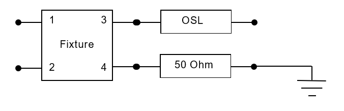
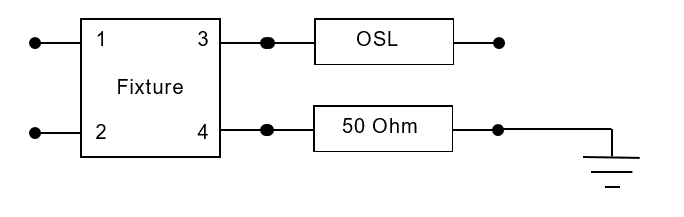
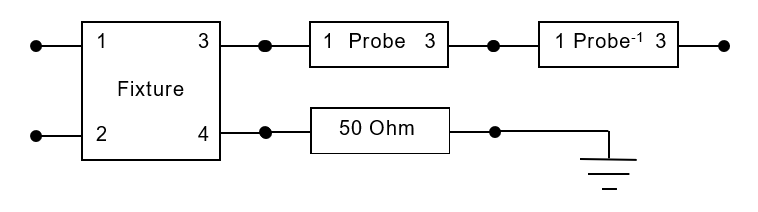
S31
- Connect Port 1 of the NA to Port 3 of the Fixture.
- Connect Port 2 of the NA to Port 3 of the Fixture.
- Terminate Port 4 of the Fixture with 50 Ohms to ground at the calibration plane.
- Terminate Port 3 of the Fixture with 50 Ohms to ground at the calibration plane.
- Measure S11Load.
- Terminate Port 3 of the Fixture with Open cal at the calibration plane.
- Measure S11Open.
- Terminate Port 3 of the Fixture with Short cal at the calibration plane.
- Measure S11Short
- Use the results S11Load, S11Open, and S11Short with the equations in Annex A.
- Implies the result S31Fixture.
S42
- Connect Port 1 of the NA to Port 1 of the Fixture.
- Connect Port 2 of the NA to Port 2 of the Fixture.
- Terminate Port 3 of the Fixture with 50 Ohms to ground at the calibration plane.
- Terminate Port 4 of the Fixture with 50 Ohms to ground at the calibration plane.
- Measure S22Load.
- Terminate Port 4 of the Fixture with Open cal at the calibration plane.
- Measure S22Open.
- Terminate Port 4 of the Fixture with Short cal at the calibration plane.
- Measure S22Short
- Use the results S22Load, S22Open, and S22Short with the equations in Annex A.
- Implies the result S42Fixture.
FEXT S-Parameters
S14
- Connect Port 1 of the NA to Port 1 of the Fixture
- Connect Port 2 of the NA to Port 2 of the Fixture
- Terminate Port 3 of the Fixture with 50 Ohms to ground at the calibration plane.
- Connect Port 4 of the NA to Port 4 of the Probe
- Measure S14 of the Fixture and Probe.
- De-embed 2 port S-matrix of the probe, SProbe4, from the measurement using the cascading 2 port de-embedding method shown in Annex B.
- T14Fixture= T14Fixture+ProbeT14Probe-1
- Implies the result S14Fixture.
S41
- Connect Port 1 of the NA to Port 1 of the Fixture
- Connect Port 2 of the NA to Port 2 of the Fixture
- Terminate Port 3 of the Fixture with 50 Ohms to ground at the calibration plane.
- Connect Port 4 of the NA to Port 4 of the Probe
- Measure S41 of the Fixture and Probe.
- De-embed 2 port S-matrix of the probe, SProbe4, from the measurement using the cascading 2 port de-embedding method shown in Annex B.
- T41Fixture= T41Probe-1T41Fixture+Probe
- Implies the result S41Fixture.
S23
- Connect Port 1 of the NA to Port 1 of the Fixture
- Connect Port 2 of the NA to Port 2 of the Fixture
- Connect Port 3 of the NA to Port 3 of the Probe
- Terminate Port 4 of the Fixture with 50 Ohms to ground at the calibration plane.
- Measure S23 of the Fixture and Probe.
- De-embed 2 port S-matrix of the probe, SProbe4, from the measurement using the cascading 2 port de-embedding method shown in Annex B.
- T23Fixture= T23Fixture+Probe T23Probe-1
- Implies the result S23Fixture.
S32
- Connect Port 1 of the NA to Port 1 of the Fixture
- Connect Port 2 of the NA to Port 2 of the Fixture
- Connect Port 3 of the NA to Port 3 of the Probe
- Terminate Port 4 of the Fixture with 50 Ohms to ground at the calibration plane.
- Measure S32 of the Fixture and Probe.
- De-embed 2 port S-matrix of the probe, SProbe4, from the measurement using the cascading 2 port de-embedding method shown in Annex B.
- T32Fixture= T32Probe-1T32Fixture+Probe
- Implies the result S32Fixture.
NEXT S-Parameters
S12
- Connect Port 1 of the NA to Port 1 of the Fixture
- Connect Port 2 of the NA to Port 2 of the Fixture
- Terminate Port 3 of the Fixture with 50 Ohms to ground at the calibration plane.
- Terminate Port 4 of the Fixture with 50 Ohms to ground at the calibration plane.
- Measure S12 of the Fixture and Probe.
- Provides the result S21Fixture.
S21
- Connect Port 1 of the NA to Port 1 of the Fixture
- Connect Port 2 of the NA to Port 2 of the Fixture
- Connect Port 3 of the fixture with 50 Ohm to ground Resistor
- Connect Port 4 of the fixture with 50 Ohm to ground Resistor
- Measure S21 of the Fixture and Probe.
- Provides the result S21Fixture.
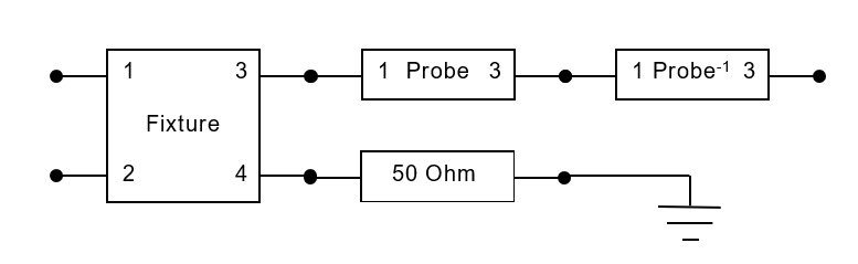
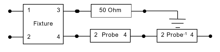
S34
- Connect Port 1 of the NA to Port 1 of the Fixture
- Connect Port 2 of the NA to Port 2 of the Fixture
- Connect Port 3 of the NA to Port 3 of the Probe
- Connect Port 4 of the NA to Port 4 of the Probe
- Measure S34 of the Fixture and Probe.
- De-embed 4 port S-matrix of the probe, including the NEXT S-Parameter S43Load and S34 Load measured in section 3.1 from the measurement using the cascading 4 port de-embedding method shown in Annex B.
- T34Fixture= T34Probe-1T34Fixture+Probe
- Implies the result S34Fixture.
S43
- Connect Port 1 of the NA to Port 1 of the Fixture
- Connect Port 2 of the NA to Port 2 of the Fixture
- Connect Port 3 of the NA to Port 3 of the Probe
- Connect Port 4 of the NA to Port 4 of the Probe
- Measure S43 of the Fixture and Probe.
- De-embed 4 port S-matrix of the probe, including the NEXT S-Parameter S43Load and S34 Load measured in section 3.1 from the measurement using the cascading 4 port de-embedding method shown in Annex C
- T43Fixture= T43Probe-1T43Fixture+Probe
- Implies the result S43Fixture.
Port Characterisation Results
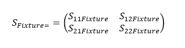
The above S parameters from the sub clauses in Section 4 can now be assembled into the S Matrix:

This matrix can be used to de-embed the fixture using the 4 port cascaded de-embedding method or converted to a touchstone and used directly with the analyser to de-embed the Fixture according to Annex C.
8 Port Method
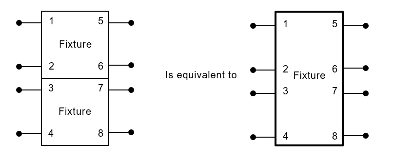
In addition to those parameters characterised for the 4 Port method, the 8 Port method considers those SE NEXT and SE FEXT couplings that occur between pairs that are part of the pair combination being tested. Such and 8 port device can be considered as being made of a pair of 4 port devices.
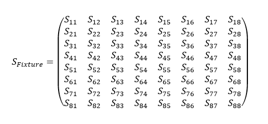
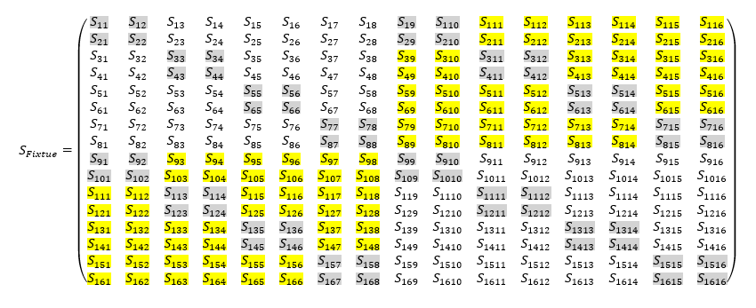
The objective of the 8 port characterisation is to populate every element of the following matrix.
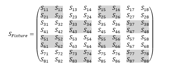
4 Port Elements of the 8 Port Matrix
Using the instructions in Section 4 it is possible to populate the highlighted elements below:
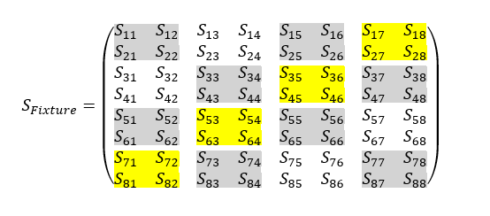
Additional Coupling Elements of the 8 Port Matrix (FEXT)
Using the instructions in Section 4.3, it is possible to populate all of the additional FEXT terms of the Fixture matrix, e.g. By terminating Port 1 and 7 of the Fixture to the VNA, and then all other ports to 50 Ohm to ground (This may be provide by VNA termination) provide the FEXT terms S17 and S71.
In this manner the Fixture matrix can be populated with the following highlighted terms.
Additional Coupling Elements of the 8 Port Matrix (NEXT Near End)
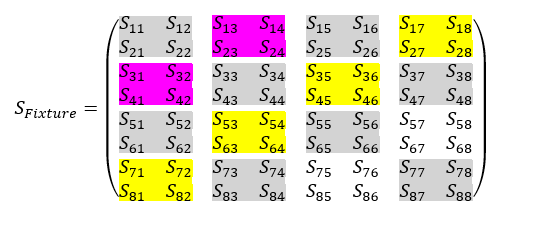
Additional Coupling Elements of the 8 Port Matrix (NEXT Far End)
The provided airplane probes, either as a 2 port probe or a 4 port probe, do not allow for connections that would allow measurement of the remaining terms of the 8 port matrix.
However, if using alternative probes or fixtures that do allow connection to Ports 5&8, 6&7, 5&7 and 6&8, a direct measurement of NEXT should be used to populate the final terms of the matrix.
If by the nature of this fixturing it is not possible to take a direct measurement, a de-embedded probe may be used to qualify these NEXT terms.
Finally, if neither measurement technique is possible, it may be assumed that the Far end NEXT and the Near End NEXT are reciprocal, in which case:
De-embedding of 8 Port Matrices
The de-embedding of 8 port matrices is identical to the 2 Port and 4 Port methodologies described in Annex B and Annex C, however the conversion from S to T parameters becomes more complicated, hence it is convenient to adopt a matrix transformation function rather than explicit equations for each term of the matrix. The details of this transformation are shown in Annex D
16 Port Method
In addition to those parameters characterised for the 4 Port method and the 8 Port method, the 16 port method considers those SE NEXT and SE FEXT couplings that occur between pairs that are part of the pair combination being tested and those that of the unused pairs.
It should be noted that in order to full describe the airplane fixture as a 16 port matrix it is necessary to use more than the 12 probes described in Section 3.
Such a 16 port device can be considered as being made of a pair of 8 port devices.
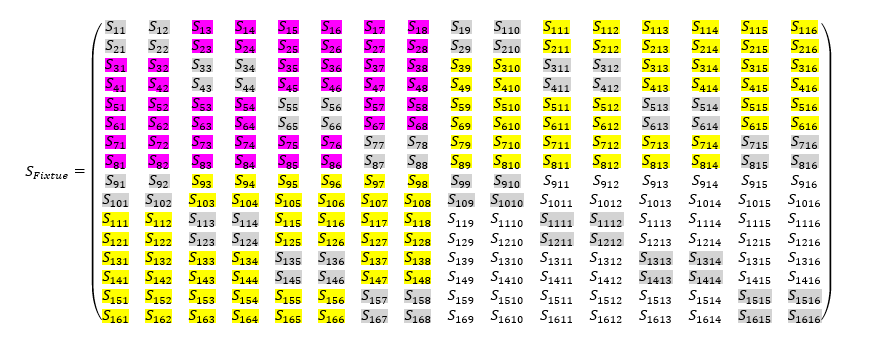
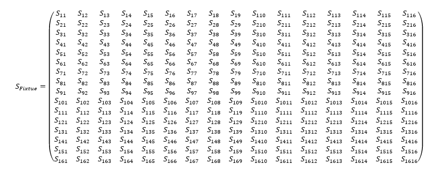
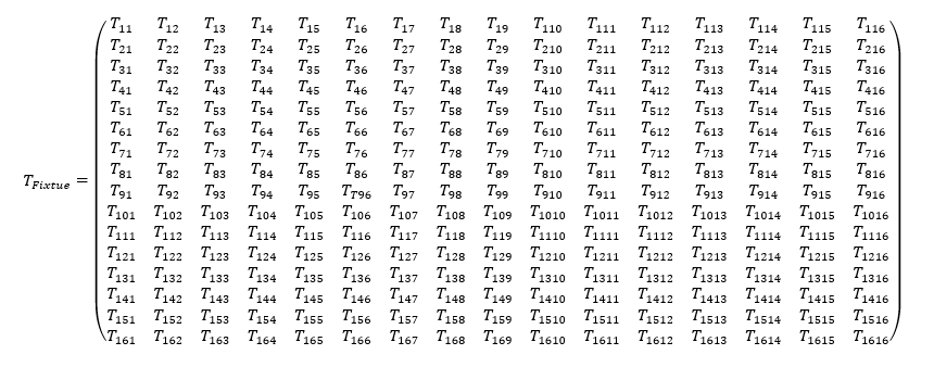
The objective of the 16 port characterisation is to populate every element of the following matrix.
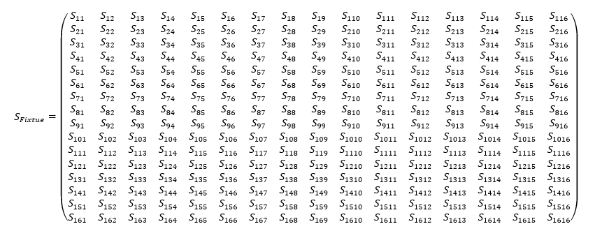
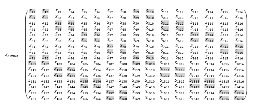
4 Port Elements of the 16 Port Matrix
Using the instructions in Section 4 it is possible to populate the highlighted elements below:
Additional Coupling Elements of the 16 Port Matrix (FEXT)
Using the instructions in Section 5.2, it is possible to populate all of the additional FEXT terms of the Fixture matrix.
In this manner the Fixture matrix can be populated with the following highlighted terms.
Additional Coupling Elements of the 16 Port Matrix (NEXT Near End)
Using the instructions in Section 5.3, it is possible to populate all of the additional near end NEXT terms of the Fixture matrix.
In this manner the Fixture matrix can be populated with the following highlighted terms.
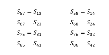
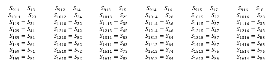
Additional Coupling Elements of the 16 Port Matrix (NEXT Far End)
Using the instructions in Section 5.4, it is possible to populate all of the additional near end NEXT terms of the Fixture matrix either by measurement or substitution.
If no measurement is possible the reciprocal relationships of near to far end NEXT are provided below.
De-embedding of 16 Port Matrices
The de-embedding of 16 port matrices is identical to the 2 Port and 4 Port methodologies described in Annex B and Annex C, however the conversion from S to T parameters becomes more complicated, hence it is convenient to adopt a matrix transformation function rather than explicit equations for each term of the matrix. The details of this transformation are shown in Annex E.
Annex A (informative)
Calculation of 2 Port Matrices from Single Ended Measurements
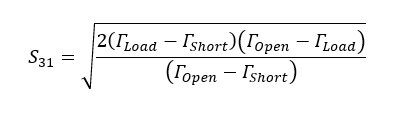
The following equations are used to derive the 2 port S-matrix based on single ended measurements.
These equations can be found in TIA 568C.2 Annex C.
It should be noted that the following calculations should be based on unwrapped phase information, this eliminates the 2*pi jumps in phase when plotted against frequency that would otherwise result in choosing the ‘wrong’ root for some frequencies in the following equations
Look at each delta between angles as frequency increases. If the delta is greater than pi, add or subtract 2*pi from subsequent angles, depending on the sign of the delta. If delta is positive, subtract 2*pi, and if negative, add 2*pi. The result of this should be a smoothly monotonic angle when plotted against frequencies, with no big discontinuities.
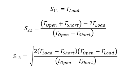
It is assumed that that S21 and S12 are reciprocal, therefore:
Using the measurements given in 3.1 we can then calculate the 2 port matrices for the two probes:
An example template and calculation is shown in the following embedded file:
Annex B (informative)
2 Port De-embedding (Cascade Method)
The following equations are used to de-embed the 2 port S-matrix of the probe from the 2-port S-Matrix of the probe and fixture measurements.
These equations can be found in TIA 568C.2 Annex C.
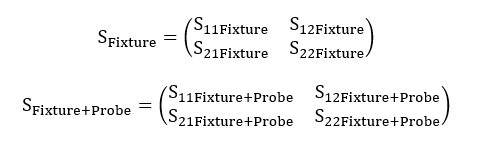
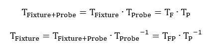
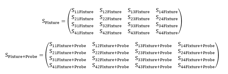
The S-Parameter Matrices of the Fixture and the Fixture+Probe are given by:
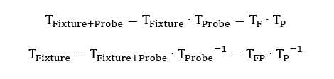
Converting to T-Parameter we state that:
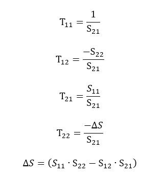
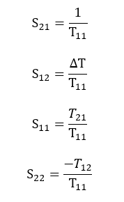
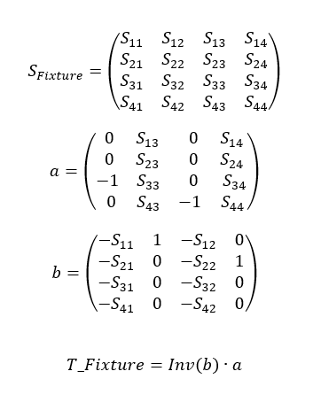
The following conversions are used to convert S-Parameters to T-Parameters:
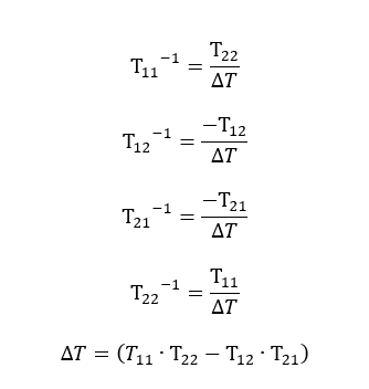
The following conversions are used to convert T to T-1:
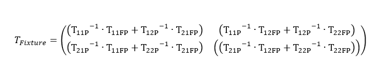
Solving the above gives:
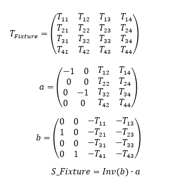
The following conversions are used to convert T-Parameters to S-Parameters:
This resolves a 2 port value for the Test Fixture:
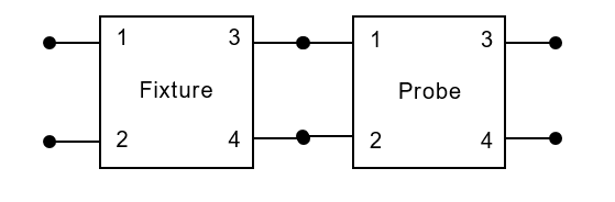
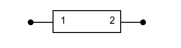
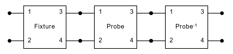
The process can be described graphically by the following diagram:
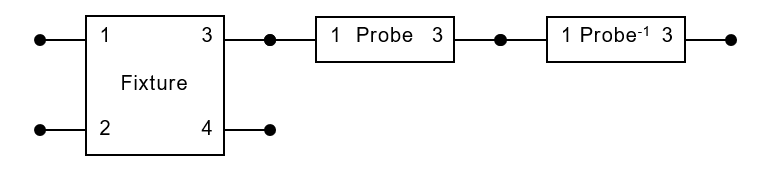
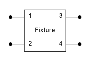
Which is equivalent to:
An example template and calculation is shown in the following embedded file:
Annex C (informative)
4 Port De-embedding (Cascade Method)
The following equations are used to de-embed the 4 port S-matrix of the probe from the 4-port S-Matrix of the probe and fixture measurements.
The S-Parameter Matrices of the Fixture and the Fixture+Probe are given by:
Converting to T-Parameter we state that:
The following conversions are used to convert S-Parameters to T-Parameters:
The following conversions are used to convert T-Parameters to S-Parameters:
This resolves a 4 port value for the Test Fixture:
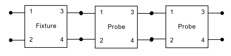
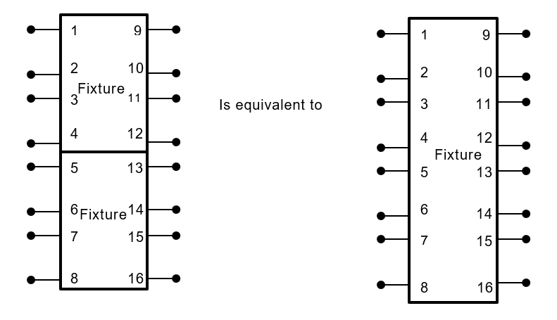
The process can be described graphically by the following diagram:
Which is equivalent to:
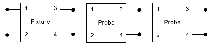
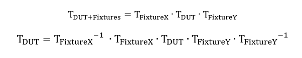
When using 2 fixtures to characterise a DUT, the process can be described graphically by the following diagram:
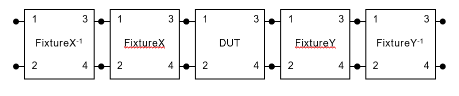
Which is equivalent to:
Converting to T-Parameter we state that:
Annex D (informative)
8 Port De-embedding (S-T and T-S Conversions)
The following conversion can be used to transform for 8 Port Fixture matrices from S to T matrices:
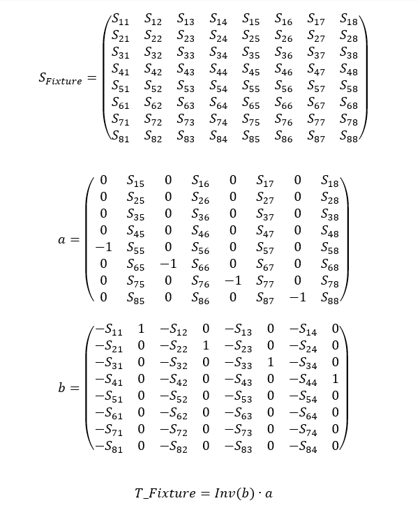
The following conversion can be used to transform for 8 Port Fixture matrices from S to T matrices:
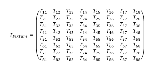
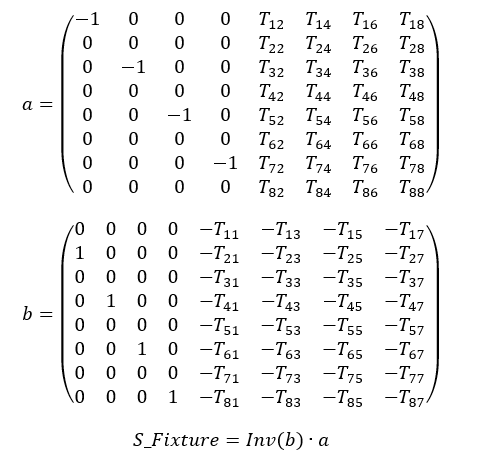
The de-embedding is performed in the same way as 2 Port and 4 Port calculations, using cascaded T matrices, See Annex B and Annex C.
Annex E (informative)
Annex A 16 Port De-embedding (S-T and T-S Conversions)
The following conversion can be used to transform for 16 Port Fixture matrices from S to T matrices:
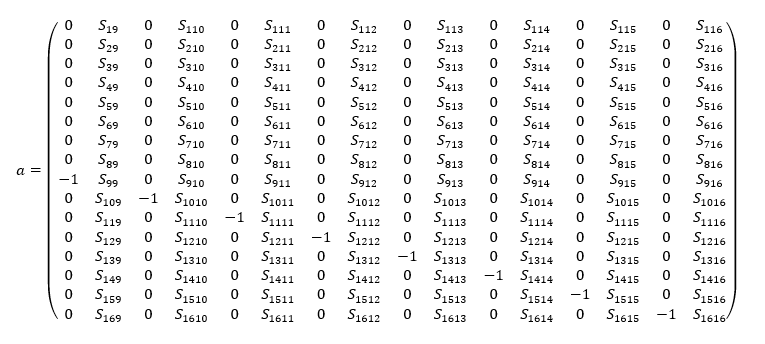
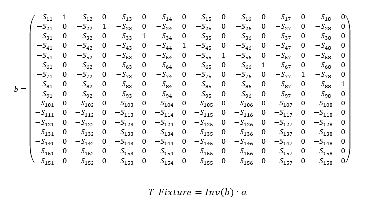
The following conversion can be used to transform for 8 Port Fixture matrices from S to T matrices:
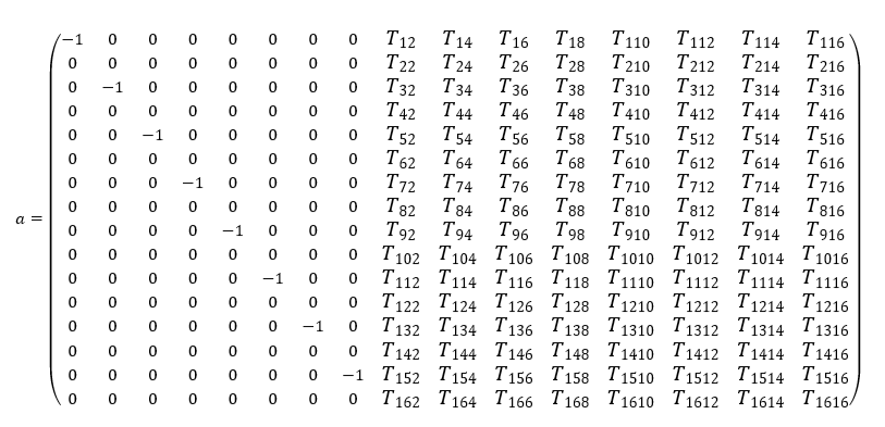
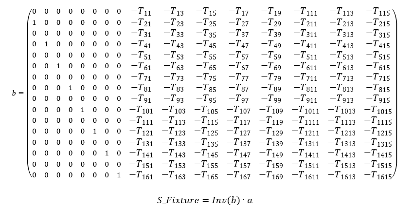
The deemebedding is performed in the same way as 2 Port and 4 Port calculations, using cascaded T matrices, See Annex B and Annex C.