Audio / Video (AV) Cabling Considerations
Download PDF
Testing Today’s AV Systems: More than Meets the Eye
Whether it’s distance learning in the classroom, a video conference in the boardroom, or digital signage in the cafeteria, more and more enterprise businesses are deploying audio-visual systems that run over structured cabling.
To support everything from high-definition video streaming and video conferencing, to digital signage and content sharing, many of these applications utilize the HDBaseT consumer electronic and commercial connectivity standard, while others may utilize Internet Protocol (IP)-based video.
When it comes to deploying and testing structured cabling to support these AV systems, there’s more than meets the eye, and it’s important to understand key performance parameters and best testing practices to ensure error-free video and image transmission.
On This Page
HDBaseT and IP Video Overview
Promoted and advanced by the HDBaseT Alliance, HDBaseT is a consumer electronic and commercial connectivity standard for transmitting uncompressed 4K video signals, audio, 100BaseT Ethernet data, power and various control signals over common category copper cabling and RJ45 connectivity up to 100 meters. This is similar to IP-based video systems that also use common category copper cabling and RJ45 connectivity up to 100 meters.
Although the cabling infrastructure for HDBaseT may look the same as IP-based video that utilizes the packet-based Ethernet protocol, it is actually based on a different protocol. While both HDBaseT and Ethernet use pulse amplitude modulation (PAM) coding technology, and HDBaseT does support an Ethernet channel, HDBaseT is not packet based data.
Further, HDBaseT systems use their own dedicated cables that connect HDBaseT transmitters to an HDBaseT receiver and are therefore separate from the data network. IP-based video signals travel across the same cabling that transmits IP-based voice and data via common Ethernet switches and routers. When it comes to HDBaseT specific equipment, everything from transmitters and receivers, to projectors and displays are certified by the HDBaseT Alliance to ensure interoperability within an HDBaseT system. An HDBaseT device connected to an Ethernet network will typically only enable its Ethernet capabilities and will not transmit audio/video.
Common Cabling, Practices and Parameters
Since both HDBaseT and IP-based video run over the same cabling media, they are deployed using the same best practices for cable handling and termination--everything from maintaining pair twist and not exceeding the bend radius to staying away from power sources. And both run over 100-meter channels.
Something else that these AV systems have in common is the fact that cable quality matters--the better the cable, the better the signal. A higher quality cable will maintain an HDBaseT or IP-based video signal better over longer distances, and for both systems, shielded cable is recommended in noisy interference-prone environments.
Another similarity is alien crosstalk. While HDBaseT can run over Category 5e or Category 6 cable, neither of these cables have alien crosstalk specifications. This isn't a problem for an individual HDBaseT channel. But just like bundles of cables transmitting high-speed Ethernet signals, bundles of cables transmitting HDBaseT can be adversely impacted by alien crosstalk. That's why it is recommended to use Category 6A for installations designed to support multiple HDBaseT cables in the same pathway.
Propagation Delay and Delay Skew
Other performance parameters to be aware of for AV systems include propagation delay and delay skew. Delay happens for all signals across all cable types, and propagation delay is the amount of time it takes for a transmitted signal to be received at the other end of the link or channel. The propagation delay in a twisted-pair copper cabling such as Category 6 or 6A is related to the nominal velocity of propagation (NVP), as well as the length of the cable and the operating frequency.
Expressed as a percentage and specified by the cable manufacturer, NVP varies based on the materials used in the overall construction of the cable itself. It characterizes how fast a signal travels down the cable relative to the speed of light in a vacuum. Since the speed of light in a vacuum is the highest speed that can possibly be achieved, the value is always below 100%, with most twisted-pair cabling in the 60 to 80% range. The lower the NVP, the greater the delay.
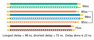
When we look at a four-pair cable where all pairs are transmitting a signal, the delay may be different from one pair to another. This is what is referred to as propagation delay skew, and it is calculated by looking at the difference between the pair with the least delay and the pair with the greatest delay.

While delay in general may be a factor of the overall cable construction, delay skew is primarily caused by the overall inconsistent pair geometry and twist rates. For example, extreme differences in twist rates from pair to pair can cause a higher delay skew. All twisted-pair copper cables exhibit some delay skew since twist rates are purposely varied to minimize crosstalk, but those that fail this performance parameter (expressed in nanoseconds) could significantly impact today’s AV applications.
While equipment can typically resolve the time differentials between pairs, when the delay skew is too high, it can result in increased bit error rates and jitter. For high resolution RGB video signals where each color is sent down a separate pair, too much delay skew can cause a jittery picture on a video displays.
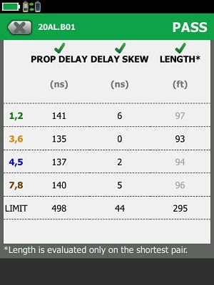
While industry standards require less than 50ns for delay skew, cables that exhibit less than 25ns like shown here are better for video applications. And given the ever-increasing use of AV systems in commercial enterprise environments, many cabling vendors are now offering “low skew” cables with delay skew values closer to 2 or 3ns.

The DSX Series CableAnalyzers measure Delay Skew as part of their range of length measurements.
Power Over Both
Both HDBaseT and IP-based AV systems also support power—one using power over HDBaseT (POH) and the other using power over Ethernet (PoE). Based on IEEE 802.3 PoE standards, POH delivers up to 100W of DC power over four pairs of category cable in conjunction with the HDBaseT video signals. Per the upcoming IEEE 802.3bt standard, PoE delivers up to 60W (Type 3) or 90W (Type 4) of DC power over four pairs of category. These levels are enough to power typical LED video displays. In fact, Energy Star™ 6.1 already restricts all TVs 60 inches or less to no more than 100W and that wattage is dropping.
POH and PoE technology opens the door for a cost-effective, easy way to deliver power to video displays, eliminating the need for AC power. However, both come with the same concerns inherent when running higher DC power over all four pairs--heat rise in cable bundles being one of the biggest. Because temperature is directly related to insertion loss, it's important to ensure that cable temperatures do not exceed the maximum operating temperature of 60°C specified by TIA standards and the recommended maximum temperature rise of 15°C for remote power applications.
To help combat temperature rise, it is recommended to reduce cable bundle sizes, use higher category or shielded cabling or reduce the channel length when delivering DC power. For example, a bundle of 60 Category 6A cables will exhibit about 12% less heat rise than Category 6. And shielded cable will perform even better due to the shield that acts as an insulator.
Certification Testing Required
While there are specific AV tools for testing resolution, frame rate and other video specifications once systems are up and running, the cabling infrastructure for both HDBaseT and IP-based AV systems need to be tested just as they would when deploying an IP-based LAN for voice and data transmission. In fact, the HDBaseT Alliance specifically states that whichever cable type is deployed, it must be tested for compliance with the appropriate TIA standard.
In other words, there is really nothing different about testing cables for HDBaseT versus IP-based video. If Category 6A cable is deployed for either system, it must be certified to meet the TIA Category 6A standard, including alien crosstalk testing--especially if you want to receive the manufacturer's warranty. In other words, you can use a copper network tester such as a Fluke Networks DSX CableAnalyzer™ Series copper cable certifier for both HDBaseT and IP-based AV deployments.
DC Resistance Unbalance Testing Recommended
Since both HDBaseT and IP-based systems also deliver higher levels of DC power via POH and PoE, DC resistance unbalance is a key parameter to test for as too much DC resistance unbalance can distort a picture.
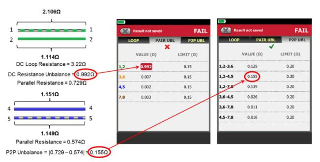
Delivering POH or PoE over all four pairs of a twisted-pair cable is achieved by applying common-mode voltage that evenly splits the current between each conductor in the pairs. For the power to be evenly split on the pair, the DC resistance of each conductor must be equal, or balanced. Any difference in resistance between two conductors is referred to as DC resistance unbalance. While devices can tolerate some DC resistance unbalance, too much unbalance causes saturation of the transformer, which can cause the video signals to become distorted. And it’s not just the DC resistance unbalance on each pair that matters – excessive DC resistance unbalance between multiple pairs also matters.
Poor workmanship and a lack of cable quality can make it difficult to achieve the common-mode voltage that allows current to be evenly split between conductors. In fact, manufacturers of HDBaseT equipment warn against the impact of inexpensive, non-compliant cables like copper coated aluminum (CCA) that exhibit variations in the diameter, concentricity and smoothness of conductors and therefore have a higher risk for unbalance.
While too much DC resistance unbalance can be avoided by choosing quality cable from reputable manufacturers and by ensuring quality workmanship with consistent terminations, it’s a good idea to test for it as it could have a significant impact on the performance of AV systems. Industry standards specify a maximum DC resistance unbalance of 3% between conductors in a pair, and the upcoming IEEE 802.3bt standard also now requires the DC resistance unbalance between any two pairs to be no more than 7% of the total parallel resistance of the two pairs.
Thankfully, just like Fluke Networks DSX CableAnalyzer™ Series copper cable certifiers are used to certify cabling plants for HDBaseT and IP-based video deployments, its ability to test for DC resistance and resistance unbalance can also verify that the cables will effectively support POH and PoE
If the difference in DC resistance between two conductors or between any two pairs is greater than the maximum allowed, there's a pretty good chance that your HDBaseT and IP-based video applications won't be picture perfect.


