Network Engineers
Support of the enterprise network falls to the Network Engineer, and the network is only as good as the copper or fiber infrastructure that supports it. Network engineers and their cabling plant need to be ready to support the latest networking technologies. And as the final escalation point for any performance problem, the Network Engineer need to have the tools necessary to determine if problems are in the network or elsewhere.
Network Engineers
Trends
High Performance Access Network Cabling
Providing users with access to high speed Ethernet requires the installation of cabling with the ability to support it. The most widely used standards for Ethernet cabling are published by the Telecommunications Industry Association (TIA) and the International Standards Organization (ISO). These standards address cabling, connectors, installed links, and testing requirements. Simply installing cabling and connectors that meet a standard will not guarantee that an installation will comply with the standard. In order for an installed link to be certified to meet a specific standard, it must fulfill the following three criteria. First, both the cabling and connecting hardware must meet their relevant standards. Second, it must be installed properly and in compliance with the standard so as not to degrade the performance link. Third, it must pass a test from a compliant field tester.
| Cabling Standard* | Maximum Frequency Specified | Supported Network Standards ** | |||||
|---|---|---|---|---|---|---|---|
| TIA | ISO | 10BASE-T | 100BASE-TX | 1000BASE-T | 10GBASE-T | 25/40GBASE-T | |
| CAT 5 | 100 MHz | ✓ | ✓ | ||||
| CAT 5e | Class D | 100 MHz | ✓ | ✓ | ✓ | ||
| CAT 6 | Class E | 250 MHz | ✓ | ✓ | ✓ | (35 m max) | |
| CAT 6A | Class EA | 500 MHz | ✓ | ✓ | ✓ | ✓ | |
| CAT 8 | Class I,II | 2000 MHz | ✓ | ✓ | ✓ | ✓ | (30 m max) |
* TIA and ISO Standards are not necessarily completely equivalent
** Support for 100 meter channels unless otherwise indicated
| Cabling Standard* | |
|---|---|
| TIA | ISO |
| CAT 5 | |
| CAT 5e | Class D |
| CAT 6 | Class E |
| CAT 6A | Class EA |
| CAT 8 | Class I,II |
| Supported Network Standards ** | ||||
|---|---|---|---|---|
| 10BASE-T | ||||
| ✓ | ||||
| ✓ | ||||
| ✓ | ||||
| ✓ | ||||
| ✓ | ||||
| Supported Network Standards ** | ||||
|---|---|---|---|---|
| 100BASE-TX | ||||
| ✓ | ||||
| ✓ | ||||
| ✓ | ||||
| ✓ | ||||
| ✓ | ||||
| Supported Network Standards ** | ||||
|---|---|---|---|---|
| 100BASE-TX | ||||
| ✓ | ||||
| ✓ | ||||
| ✓ | ||||
| ✓ | ||||
| ✓ | ||||
| Supported Network Standards ** | ||||
|---|---|---|---|---|
| 1000BASE-T | ||||
| Supported Network Standards ** | ||||
|---|---|---|---|---|
| 10GBASE-T | ||||
| (35 m max) | ||||
| Supported Network Standards ** | ||||
|---|---|---|---|---|
| 25/40GBASE-T | ||||
| (35 m max) | ||||


* TIA and ISO Standards are not necessarily completely equivalent
** Support for 100 meter channels unless otherwise indicated
Wireless Ethernet and Cabling
Due to the rapid growth of ever-more powerful mobile devices, enterprise networks are struggling to keep pace with rising bandwidth demands. Adoption of advanced wireless connectivity technologies, such as 802.11ac Wi- Fi (with theoretical speeds of over 2 Gpbs) and small cells requires that network-access speeds must move beyond their designed limits of 1 Gbps.
Upgrading to 10GBASE-T would address this issue, but the vast majority of installed cabling is Cat 5e / Class D, so this cable would need to be replaced with Cat 6A or better – an expensive proposition. To address this issue, the NBASE-T Alliance was formed with the goal of breathing new life into existing enterprise network infrastructure. The Alliance has released specifications that define 2.5 and 5 Gigabit per second (Gb/s) speeds at up to 100 meters using the large, installed base of Category 5e, 6, and 6A copper cabling in enterprise networks. However, not all installations of Cat 5e cabling can support NBASE-T technologies, so certification of the cabling to these standards is recommended in order to prevent costly failures when turning up new Wi-Fi installations.
Power Over Ethernet
Local power is not always accessible for wireless access points, IP phones, and other network devices that may be deployed in ceilings, lobbies, stairwells, and other remote areas. Adding power outlets near these devices may be extremely difficult and costly. Why not give these devices network connection and power in the same cable? This question is resolved by PoE technology. PoE is a technology designed to deliver power to networking devices using existing data communications cabling. Multiple PoE standards can supply power of up to 25.5 watts, while non-standard schemes can deliver 60 watts or more.
However, not every cable can support every level of power. Worse, many cables can deliver power intermittently, which can lead to problems which can be extremely difficult to troubleshoot. Certifying cable to make sure it meets the relevant standards is the easiest way to prevent these problems. Specialized measurements, such as resistance unbalance found in the DSX series, can be invaluable in troubleshooting these problems.
Fiber Performance - MPO
With the growth of big data, virtualization and higher bandwidth speeds in data center fiber backbone links to 40 and even 100 Gbps, most data centers today are standardizing on multi-fiber push-on (MPO) connector solutions. Despite the fact that pre-terminated MPO fiber cables are manufactured and tested by vendors to comply with ANSI/TIA and international standards, there are many factors that can potentially impact performance. Installation can damage the cables. MPO connectors are harder to clean than duplex connectors. Their much larger surface area makes it easier to move contaminants from one fiber to another within the same array during the cleaning process. 40 and 100 Gbps MPO fiber applications also have much lower loss budgets so it’s important to ensure the highest testing accuracy as possible.
Field testing is the only way to ensure that MPO links meet the application performance requirements. Unfortunately, testing a 12-fiber MPO fiber link with a duplex tester is extremely time consuming, requiring about 15 steps with a 3 jumper method and the use of MPO to LC fan-out cords that separate the 12-fiber cable into single fiber channels.
Testers with an on-board MPO connector take the complexity, time and inconsistency out of MPO testing—eliminating the need for the fan-out cord or cassette. Fluke Networks’ MultiFiber Pro is the first tester to offer this functionality with the ability to scan all 12 fibers simultaneously and display test results in an easy-to-read bar graph. The MultiFiber Pro even has the ability to identify each fiber of the MPO, providing more precise, per-fiber data and reporting to improve MPO connectorverification and troubleshooting.
Best Practices
Preventing Problems – Qualification and Certification
Testing cables when installing them or when upgrading networks is the best way to prevent problems. There are two approaches to testing installed cabling.
Qualification testing is determining whether the cabling has the qualifications to do something—in other words, support a certain network speed or application. While a “Pass” on certification testing also ultimately indicates the ability to support a network speed or application per the standards, qualification testing does NOT officially recognize that a cabling link is standards compliant. Qualification testing might be used to determine if a link can support 1000BASE-T, 10GBASE-T, VoIP, PoE or other applications.
Certification testing is typically done by the original installer amd is typically required in order to receive the manufacturer’s warranty. This process determines if a link is compliant with a specific Category or Class of cable as determined by well-defined parameters outlined by relevant standard bodies. For instance, certification testing will determine if your link is compliant with Telecommunications Industry Association Category 6A or International Standards Organization Class EA standards. To certify a link to a standard, a certification tester must test for all of the specific parameters required by the standard. For copper, this includes parameters that go well beyond length, continuity and wiremap testing. We’re talking about parameters such as insertion loss, return loss, near-end crosstalk (NEXT), power sum NEXT, equal-level far-end crosstalk (ELFEXT), attenuation-to-crosstalk ration (ACR) and more. For fiber, it means testing for continuity, polarity, length and insertion loss (Tier 1) or backscatter, reflectance, optical return loss (Tier 2) and more.
Preventing Problems - Documentation and Reporting
Certifying a cabling installation doesn't mean anything without the burden of proof. Documenting the results is the only real way to ensure installation accountability and integrity, resolve disputes and facilitate more efficient troubleshooting.
Even if the customer or a manufacturer's warranty doesn't require documented test results, documentation is still a best practice and your best protection. If you certify a cabling installation that later fails and you don't have the documentation to prove it, how else do you provide evidence that the cable was functioning properly and that it met the specification when you were done with the job?
With today's documentation software, there is no excuse for skipping this critical last step. And it's a good idea to include plot data in your reports. Graphical depiction of measured test parameters is required for true certification testing and typically mandatory for a manufacturer's warranty. These graphs show valuable information about the cabling performance and can be a valuable tool for troubleshooting.
Preventing Problems – Labeling
Without labeling, your documentation will be of little use later on. The ANSI-TIA/EIA 606A labeling standard exists for a reason, and it goes hand in hand with documentation. That is why every work area outlet must be labeled with the floor, telecommunications room, patch panel and port from where it originates.
If you need to troubleshoot a specific link at a later date and check against its original test results, you will need the link's label at the customer location to correspond to the documentation. In fact the 606A standard says that documentation without labeling and labeling without documentation does not equal administration.
Troubleshooting Access Networks
With cabling being the leading cause of network failures, having the right tools and knowledge can keep network outages to a minimum. The right tool can make it easy for even non-experts to track down tough problems.
The most basic cable test tools perform verification - assuring that all wires in a cabling link are connected to the proper termination points and not to any other conductors. Better verification test tools also verify wire pairing and detect installation defects like “split pairs”. Verification test tools may also assist in troubleshooting by providing a toner to locate a cabling link or a Time Domain Reflectometer (TDR) to determine length of a cable or distance to a break or short circuit.
Next are Qualification test tools, such as the CableIQ™ Qualification Tester, which include all the capabilities of verification test tools but they are more powerful in that they perform an assessment of the cabling bandwidth and identify defects that affect the bandwidth.
Certification tools are the most sophisticated tools and provide “Pass” or “Fail” information in accordance with industry standards. They can also troubleshoot highly difficult problems such as unbalance, which can lead to PoE issues.
Preventing Problems - Fiber Cleaning and Inspection
Fiber optics inspection and cleaning is growing in importance as links with increasingly higher data rates are driving decreasingly small loss budgets. With less tolerance for overall light loss, the attenuation through adapters must be lower than ever before. This can be achieved by properly inspecting and cleaning fiber optic cables when they are installed or while making moves, or changes.
Both optical and video scopes can display the contamination or damage that can wreak havoc on fiber communications. Optical microscopes incorporate an objective lens and an eyepiece lens to allow you to view the end-face directly through the device. Video microscopes incorporate both an optical probe and a display for viewing the probe’s image. Probes are designed to be small so that they can reach ports in hard-to-access places
Many people have their own approaches for cleaning end-faces, including some suboptimal approaches such as blasting the fiber optic cable with canned air, or using Isopropyl alcohol (IPA). Fiber-specific solvents are superior at dissolving virtually any contaminate lurking on a fiber end-face and have tailored evaporation rates that give them time to work yet disappear before mating. Click cleaners make it easy for anyone to perform basic cleaning quickly.
Troubleshooting Fiber Networks
Troubleshooting fiber problems requires specialized equipment that ranges from very basic to highly sophisticated. Many network engineers don’t invest in the equipment due to its cost and complexity, instead hiring experts to troubleshoot fiber problems. However, newer tools are available that reduce costs, are simple enough for the occasional user, and can thereby eliminate the cost and wait for the expert.
The most common tool for testing fiber is the combination of Light Source and Power Meter. This pair is used to measure the loss of fiber optic power across the length of the link. If the loss is too great, the signal can’t get through with enough power to be “seen” at the far end.
Unfortunately, the Light Source / Power Meter combination can’t identify the cause of a fiber optic fault. Since connector contamination or damage are likely sources of fiber loss, a manual and time consuming inspection of each connection in the link may find the problem. Visual Fault Locators send a widely dispersed light down the cable, which can be used to find disconnected cables, breaks or even too-tight bends, but require a visual inspection of the entire length of the cable.
The ultimate fiber troubleshooting tool is the Optical Time Domain Reflectometer (OTDR). By sending a pulse of light down the cable and monitoring reflections, if can show the magnitude and distance to every imperfection in the link. Older models displayed complex traces which required a significant level of expertise to interpret. Newer models can interpret the traces and display simple diagrams indicating where the problems are. A recently introduced class of basic troubleshooters uses OTDR-like technology to display the distance to faults along the link.
Tools and Solutions
OptiFiber® Pro OTDR
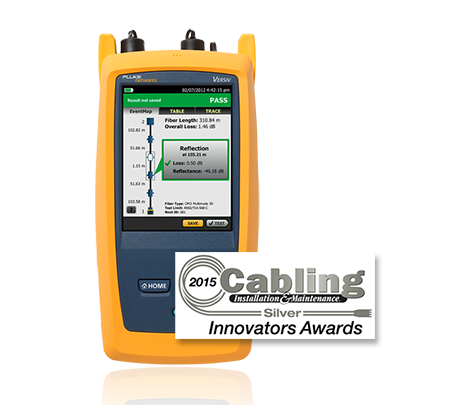
OptiFiber Pro is the first OTDR built from the ground up for enterprise fiber optic cabling testing. OptiFiber Pro OTDR is focused on reducing costs while enhancing productivity and improving network reliability.
Fiber Testing Tools
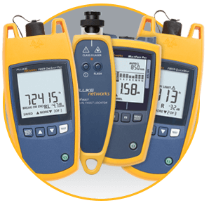
Installing and troubleshooting fiber optic networks doesn’t have to be difficult. Whether you need to certify, check for loss, find bends or breaks or know the length of the cable, the right tool can make the task easy.
- Light Sources and Power Meters – Quickly determine the loss of a link.
- Fault Locators – Find fiber length and distance to faults for a fraction of the cost of an OTDR
- Visual Fault Locators – Let you see breaks and excessive bends in the fiber cable
Fiber Optic Cleaning Kits
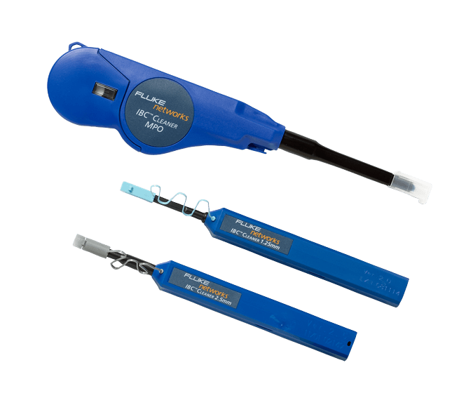
Dust - just because you can’t see it doesn’t mean it’s not there.
The only way to know it’s clean is to inspect it before you connect it. And if it’s dirty, it needs to be cleaned with the right tools or you might just make it worse.
Copper Testing Tools
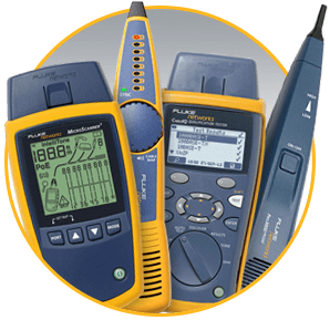
Companies expect their twisted pair cabling to work flawlessly, but corners cut during design, installation and testing result in network downtime which translates to wasted resources and lost revenue. This can be avoided by cable installers that are capable of installing copper cabling systems and locating faults quickly. From 100BASE-T to tomorrow’s advanced twisted pair technology, Fluke Networks is the industry’s most trusted partner for cabling testing.
Copper Termination Tools
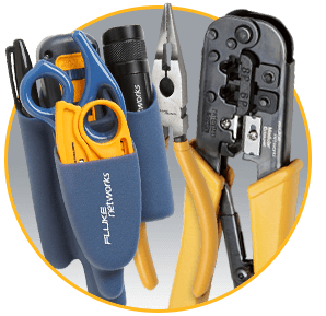
Tools and test sets for installing, verifying and maintaining voice, video and data services. Voice, video and data installation starts with having the right tool. Fluke Networks offers the most reliable network installation tools on the market—each one designed to streamline the job and make you more productive. Our complete line of termination tools and test sets meet the demands of technicians by providing reliability, maximum ruggedness, data protection and flexible options for every budget.
Related Resources
Fluke Networks provides many resources to help our customers solve (Network Engineers) challenges. Some require a simple registration. See a complete listing of webcasts, white papers and application notes for other topics.
Top 5 reasons Upgrading to Versiv will save you money
Executing Highly Accurate Fiber Measurements in a Fraction of the Time
OptiFiber Pro Datasheet
Fiber Testing Best Practices Pocket Guide
How to Choose a Datacenter OTDR
OptiFiber Pro is Fast
OptiFiber Pro is Easy
OptiFiber Pro is Powerful
Fiber Cleaning: How to Properly Clean Optical Fibers
Getting started with OptiFiber Pro Playlist
©2006-2021 Fluke Corporation。保留所有权利。
RM2011, 20/F, SCITECH Tower, 22 Jianguomenwai Avenue, Chaoyang District, Beijing, China
地址:北京市朝阳区建国门外大街22号赛特大厦20层2011室
联系电话:400-8103435
沪ICP备11037028号-15![]()


