Data Centers Make Networks Work
The data center is the heart of every enterprise network. It enables the transmission, access, and storage of vast amounts of vital information.
On This Page
- What Is Data Center Cabling?
- Data Center Cabling Standards
- Key Challenges in the Data Center
- Cabling Considerations for Data Centers
- Keep Learning
What Is Data Center Cabling?
Data center cabling connects enterprise local area networks (LANs) to switches, servers, storage area networks (SANs), and other active equipment that supports all applications, transactions, and communications. It’s also where the LAN connects to service provider networks that provide access to the internet and other networks outside of the facility.
Data Center Cabling Standards
Standards such as ANSI/TIA-942, ISO/IEC 24764, and ANSI/BICSI 002 provide minimum recommendations for the design and deployment of data centers, including pathways and spaces, backbone and horizontal cabling, redundancy and availability, cable management, and environmental considerations.
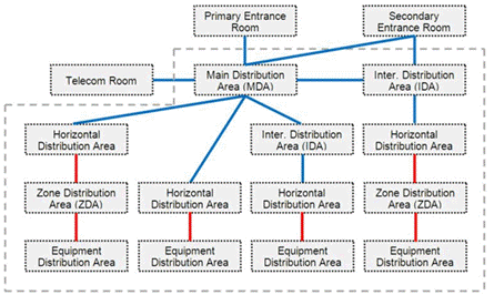
These standards also outline specific functional areas of the data center:
-
• Entrance room (ER): Sometimes referred to as the entrance facility, the ER is located inside or outside the data center. This is where the service enters the data center, providing the demarcation point to service provider networks and backbone cabling to other buildings in a campus environment.
-
• Main distribution area (MDA): As the central point of distribution, the MDA houses core switches and routers for connecting to LANs, SANs, and other areas of the data center, as well as telecommunications rooms (TRs) located throughout a facility.
-
• Horizontal distribution areas (HDA): The HDA is the distribution point for connecting servers in the equipment distribution area (EDA) to core switches in the MDA. Fiber backbone uplink cabling from the MDA terminates here at fiber patch panels within cross-connects or interconnects that connect aggregation and access switches. While most data centers will contain at least one HDA, a top-of-rack (ToR) architecture where access switches connect directly to servers in the same cabinet eliminates the HDA.
-
• Equipment distribution area (EDA): This is where servers reside. These servers connect to switches in the HDA via horizontal cables terminated at copper or fiber patch panels or via direct connections to ToR switches in the same cabinet.
-
• Intermediate distribution areas (IDA): These optional spaces, sometimes called intermediate distributors, are typically found in larger data centers with multiple floors or rooms that distribute fiber links from the MDA to various HDAs and EDAs via aggregation switches.
- • Zone distribution area (ZDA): These optional spaces are typically not found in enterprise data centers. The ZDA does not contain active equipment, but it can serve as a consolidation point within the horizontal cabling between HDAs and EDAs to facilitate future growth and reconfigurations.
This diagram from the TIA-942 data center standard shows the various spaces connected with backbone (blue) and horizontal (red) cabling.
Key Challenges for Data Centers
The data center is essential to an enterprise’s operation and houses an ever-increasing amount of mission-critical equipment. There are several key considerations and challenges to ensuring reliability and performance for current and future needs. Let’s take a look at a few of the more important ones.
Growth and Scalability
As businesses strive to compete in a data-driven world, more cloud and colocation data centers appear. They provide the means for deploying new systems and services faster, allowing businesses to respond quickly to changing needs and expand capacity without the need to upgrade in-house enterprise data centers. Many enterprise businesses trend toward a hybrid IT approach, keeping some IT resources in-house or in a secure colocation data center (particularly where there’s a need to maintain data control), and letting others reside in the cloud. Cloud resources use software-as-a-service (SaaS), while colocation data centers typically offer infrastructure-as-a-service (IaaS).
Redundancy and Availability
Redundancy involves having duplicate components (such as equipment, links, power, and pathways) that ensure functionality if any one component fails. It’s often defined using the “N system,” where N is the baseline for the number of components required for the data center to function.
- ○ N+1 redundancy means having one more component than is needed to function.
- ○ 2N redundancy means having double the number of components required.
- ○ 2N+1 redundancy is double the amount, plus one.
The Uptime Institute’s Tier levels call out the N level required for the various levels of data center availability. The BICSI 002 availability class system also refers to the N level.
Power, Cooling, and Efficiency
With an increased focus on sustainability, the Green Grid also now has a Carbon Usage Effectiveness (CUE) metric that determines the amount of greenhouse gas (GHG) emissions produced per unit of IT energy consumed within a data center. It also has a Water Usage Effectiveness (WUE) metric that measures the ratio between water used in the data center (for water-based cooling, humidification, etc.) and the energy consumption of the IT equipment.
Cooling maintains an acceptable equipment operating temperature and prevents hot spots that could adversely impact equipment lifetime and reliability. ASHRAE recommends an operating temperature range of 18° to 27° C (64° to 81°F) for data centers. Cooling impacts efficiency, accounting for 30% to 50% of total data center energy consumption.
- ○ Preventing cold inlet air and hot exhaust air from mixing can allow higher return air temperatures, which improves the efficiency of data center cooling systems and prevents over-provisioning of power-hungry air conditioning units.
- ○ Using a hot aisle/cold aisle configuration in the data center is a passive way to prevent mixing hot and cold air. It involves lining up rows of cabinets so that cold air intake is optimized at the front of the equipment and hot air exhausts from the back of the equipment to the cooling return system.
With higher processing power and heat generation, some data centers need more effective ways to prevent mixing hot and cold air.
- ○ Passive containment systems completely isolate hot and cold aisles, using roof panels to isolate the cold aisle from the rest of the data center (“cold aisle containment”) or vertical panels to isolate the hot aisle and return the hot exhaust to the overhead return plenum (“hot aisle containment”). Containment systems can also be active, using fans to pull hot air from the cabinet into the hot aisle.
- ○ Some high-performance computing environments (such as hyperscale data centers) with extremely high power densities are turning to liquid cooling solutions for better heat conduction. These solutions include rear door heat exchangers that cool hot exhaust air as it passes over liquid-filled coils at the rear of the equipment cabinet, liquid immersion that surrounds equipment with coolant that circulates through a chilled water loop, and cold plate or direct-to-chip cooling where coolant is pumped to small cold plates that attach directly to heat-generating components within equipment, such as CPUs.
Cabling Considerations for Data Centers
Regardless of the size and type of the data center, the switching topology and the applications, the underlying cabling infrastructure is crucial for ensuring the reliable, high-bandwidth links that are needed to connect data center equipment across various functional areas. There are several considerations when it comes to data center cabling.
Cable Management
- ○ Moving high-density cables overhead is one strategy for preventing cable congestion in underfloor pathways that can block the movement of cold air.
- ○ Within the cabinet, horizontal and vertical cable management solutions help properly route and organize cables in and around equipment to maintain proper airflow.
- ○ A solution for copper cabling, which is larger than fiber and can block more airflow, is to use smaller-gauge copper patch cords.
- ○ Horizontal and vertical cable management is critical to maintaining proper bend radius and strain relief. Exceeding the bend radius of cabling and placing strain on the cables can degrade performance or lead to non-functioning links.
Cable Testing
- ○ Backbone cabling links between the ER, MDA, and HDA will almost always be single-mode and multimode fiber.
- ○ Horizontal cabling between the HDA and the EDA (switch-to-server links) will be Category 6A or higher copper connections or multimode fiber.
- ○ If the EDA uses a ToR configuration, SFP+ or SFP28 twinax direct attach cables (DACs) are often used for these connections. Testing SFP/QSFPs modules involves verifying that power is properly delivered. To delve deeper into what is typically tested in each functional area of the data center, download our free white paper, In the Data Center — Where and What Am I Testing?
Fiber Loss Budgets
Industry standards specify the amount of insertion loss allowed for fiber applications to function properly, and higher-speed applications such as 40GBASE-SR4 and 100GBASE-SR4 have much more stringent insertion loss requirements.
Data centers determine their fiber loss budgets based on distances between the functional areas and the number of connection points along the way to ensure that they stay within these requirements. Accurately determining a fiber loss budget requires knowing the insertional loss values of specific vendors’ cables and connectivity.
Basic fiber testing (Tier 1 certification) measures the insertion loss of the entire fiber link in decibels (dB) using an optical loss test set (OLTS). Cable manufacturers almost always require Tier 1 certification to acquire a system warranty. Some may also require Tier 2 certification using an optical time domain reflectometer (OTDR) that provides insight into the loss of specific connection points and the cable. Using an OTDR followed by an OLTS offers a complete testing strategy that characterizes the entire link and ensures the most accurate insertion loss testing.
Staying within the insertion loss budget for fiber is also highly contingent on the cleanliness of fiber end faces, as contamination remains the number one cause of fiber-related problems and test failures in data centers. Even the slightest particle on the core of a fiber end face can cause loss and reflections that degrade performance. Cleaning and inspection are therefore critical steps in data center fiber terminations.
MPO Cabling and Connectivity
Testing MPO cabling links with an MPO-capable fiber tester is recommended to save time, eliminate complexity, and improve accuracy.
For data center links to function, they must maintain proper polarity such that the transmit signal at one end of a link matches the corresponding receiver at the other. Ensuring proper fiber polarity can be more complex with MPO connectivity because multiple transmit and receive fibers must correspond correctly. MPO-cable testers that check for correct polarity can help eliminate polarity mistakes.
Keep Learning
- • Testing on the Edge
- • Single-mode Fiber is On Rise. Are You Ready?
- • The A-B-C’s of Fiber Polarity
- • The Road to 200 & 400 Gig is Already Paved (and Traveled)
- • Testing in the Data Center Spaces
- • The Skinny on 28 AWG Patch Cords
- • Designing to Application Limits
- • Cross Connects and Interconnects in the Data Center
- • Bandwidth and Data Rates
- • The Rise of the Hyperscale Data Center
- • RJ-45: A Mainstay in the Data Center
- • Testing Cabling with MPO Connectors — What’s New?
- • Benefits of Using 8-Fiber Plug and Play MPO Solutions

