Split Pair Identification
A “Split Pair” is a wire map error where one leg of a pair is terminated in a connector on the pin of a different pair. The effect can be hard to spot, the conductors are lined up one to one on each end of a cable, but the conductors are not in pairs. This simple twisting of the conductors, invented by Alexander Graham Bell, stops the radiation of interference from the pairs and provides immunity to outside interference such as EMI. If the conductors are not paired, there will be significant crosstalk in the link.

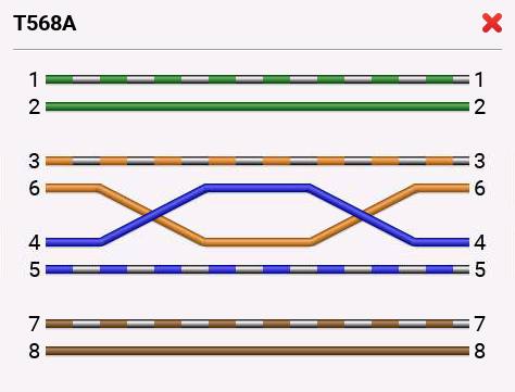
Figure 1. Split Pair Example
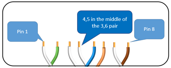
In Figure 1, we can see that the Orange conductor is connected to Pin 6 at both ends, and the blue conductor is connected to Pin 4 on both ends, but 3,6 and 4,5 are not pairs. This means that these conductors will be more susceptible to interference or noise and may not be able to provide the reliable communications you are expecting.One of the main causes of a split pair is a patch cord that has the pairs terminated incorrectly. Here we see an example of the T568A Outlet Configuration. Notice that the 4,5 pair sits in the middle of the 3,6 pair in the RJ-45 plug. We need to terminate patch cords in either the T568A or B sequence to assure proper use of the pairs, and backwards compatibility of the connectors with all others.

Figure 2, correct T568A termination
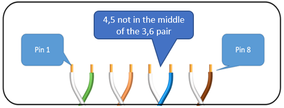
Incorrectly terminated pairs, adjacent to each other, create the split pair seen in Figure 1:

Figure 3, incorrect pair alignment in RJ-45 plug
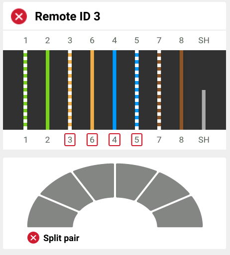
LinkIQ will detect a split pair and it will be reported as seen in Figure 4 with the incorrect conductors outlined with a red box. Additionally, there is text that identifies the problem as a Split Pair in the bottom left corner.

Figure 4, Split Pair reported on LinkIQ
LinkIQ’s ability to detect a split pair offers significant benefits over a simple LED type wire map or continuity tester.
See Related Article:


